embedded machine vision project
Project outline
This project was a subcontract for a company that had developed a traffic monitoring and size estimating system using LiDAR. The company wanted to integrate a camera into their system to capture images of vehicles detected by the LiDAR sensor.
Their equipment was deployed in the field in an environmental enclosure and had limited power budget and compute power - the processor was a Raspberry Pi 3B.
Given the wide detection arc of the LiDAR sensor, my primary task was to capture multiple images of the vehicle while it was within the detection zone. After the vehicle had exited the detection zone, I used a vision algorithm to select the best image from the captured stream.
The vision algorithm is a variant of algorithms used by security camera systems to perform object detection based on scene averaging. I wrote this code using the general algorithms but without reference to any prior embodiment.
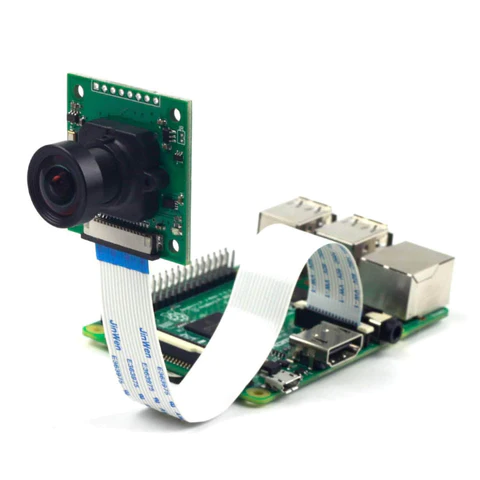
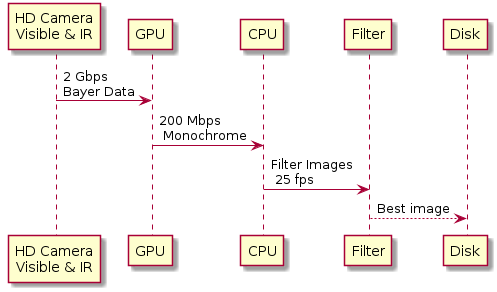
The Raspberry Pi 3B offers the capability to connect a visible and infrared capable camera through a high-speed, closely coupled data bus. The Raspberry Pi 3B also features a GPU that plays a crucial role in the initial processing of the image stream. The GPU efficiently reduces the potential data rate of 2 Gbps of raw Bayer data down to a more manageable 200 Mbps of monochrome or colour data.
Data Flow
As explained later, this is the basic data flow.
Project Appreciation
In this context, the term "appreciation" refers to the process of evaluating and understanding various factors, considerations, and available resources before deciding on a course of action for the project. It involves assessing the advantages and disadvantages of different options and rapidly eliminating weaker or riskier options to develop a single outline plan.
There will always be constraints on a project such as budget, start time, latest end time, and resources. The appreciation needs to take into account those constraints.
This project was on a time budget so I had to make development decisions that would lead to a quick implementation with minimum risk of ‘rabbit holes’ – that is problems that pop up and have to be solved before the actual task can be completed.
Here are the factors used in my appreciation process:
The camera drivers provided for Raspbian are somewhat obscure and documentation is varied
The Raspbian O/S has drivers that are most often called by python scripts
There is a community using the cameras mainly through python, but the quality of blogs and forums is poor
There is an existing C++ API called RaspiCam that could be evaluated very quickly
As this was a machine vision project using something like OpenCV was a distinct possibility
I have no experience in OpenCV and sensed there would be many rabbit holes in getting up to speed with it
I had already used machine vision systems for object detection long before OpenCV and I was very familiar with the algorithms I would need which are basically a set of simple high speed vector operations on image matrices
There was a limited time budget for the project
I am fast at generating reasonable C++ code – many hundreds of code lines on a good day.
My outline plan became:
Implement my own machine vision functions in original C++
Integrate the Raspicam API
Incrementally develop and test functionality
Develop a multithreaded communications subsystem
Integrate all into an image processing train.
My known unknowns included:
Potential issues with RaspiCam
Performance of the algorithm in terms of frames per second
My available mitigation strategies were:
Using the Raspberry Pi drivers directly
Modifying the algorithm and/or employing native vectorization to enhance performance
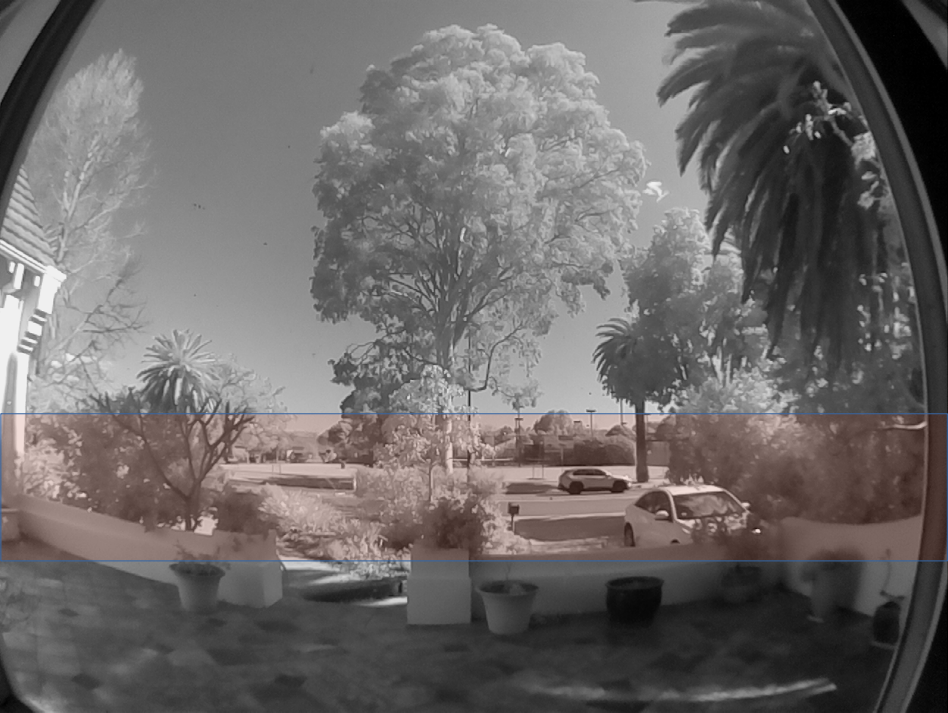
Test Camera Setup
The test camera was set up to observe a busy roadway by day and night. The camera has a fisheye lens that captures a far larger image than needed for vehicle detection. As a consequence, the main image is 'sliced' to a very wide but not very high image. The slice is what is analysed by the proceessing train after resolution reduction. However, the entire high resolution slice is what is recorded.
The capture slice is highlighted in peach
Software Architecture
As part of the development process, I created source and sink base classes and then generated derived classes for:
Sources including existing images on disk, randomly generated sources, and images from the camera
Sinks including X-windows screen, file
The main application consists of
A mainline thread that reads configuration and configures class instances
A communications thread instance that listens for commands via UDP
A loop in the main thread that waits for commands from the communications thread while updating the reference scene or actively capturing a sequence of images
Processing Architecture
Data Sequencing
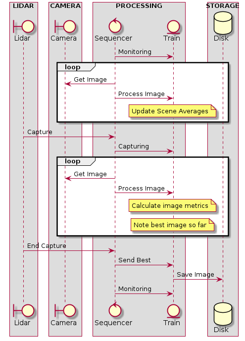
In the monitoring mode of operation the sequencer captures images and feeds them to the processing train. The train uses these images to construct a time average of the scene and detect areas of high noise such as waving tree branches.
The averaging process is configured to change slowly by adding in a fraction of the new image to the reference scene. This is set so that the average scene represents the last few minutes of the scene and so can take into account changes in sun angle or cloudiness.
In the capturing mode of operation the sequencer feeds images to the train which filters regions which had been noisy in the past. It then applies a weight filter to the image to favour ones that have the target vehicle in the centre of image. Finally an image metric based on image variance from reference is used to grade the usablity of the image.
When the lidar detects the vehicle has exited the capture zone the sequencer saves the best image in this sequence to storage.
This architecture used a LiDAR but the software alone is quite capable of detecting vehicles entering and leaving the capture zone.The software can also generate an output where the background is removed and only images of the vehicles are output. These could then be used as an input to an AI vehicle recognition system
Thread communications
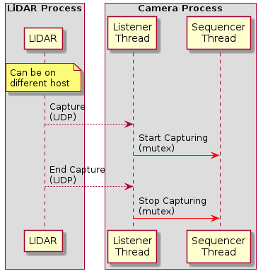
Image Processing train
The image processing train is a number of matrices matching in size to the captured image. They are applied to the captured image to filter, weight, and calculate derived values such as image variation.
The video below shows taps into several matrices maintained in the image processing train
Note the frame rate is quite low as it is being rendered on X-Windows. Normal frame rate is 25-40 fps
- MAGENTA: Long term areas of high variance - mostly tops of passing vehicles
- GREY: Long term reference image adjusted slowly over time
- GREEN: Image variance from reference image - can be used for object detection
- YELLOW: Image after masking
- BLUE: Mask applied to image
NB The roadway is excluded from mask generation as the roadway is where variation is expected and useful. Other areas such as tree branches contribute to the mask.
Source Code
The source code directory is password protected with user guest and password incamera
The code is at Code Samples